
Oil Circuit Breaker (3ø, 3pole,400 A)
This set up is designed to study the working principle of OCB and to test the OCB (Oil circuit breaker ) under over current fault and Earth Fault conditions . This set up consists of
- OCB ( Oil Circuit Breaker)-11KV
- OCB Test Kit with Panel set up
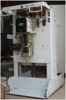
OCB (Oil circuit Breaker)
- Capacity : 11KV
- Type : Draw out Type
- Rated Current : 400A
- Rated Voltage : 415V, 3 Phase, 50HZ
- Rated Insulated Voltage : 690 V
- Rated S.C Breaking : 6 KA
- of Pole : Three Pole
Other Features
Housing: The OCB is housed in M.S. Cubicle box with conduit plugs are provided with side entry of cables. Provision for termination of contacts is made inside the cable box
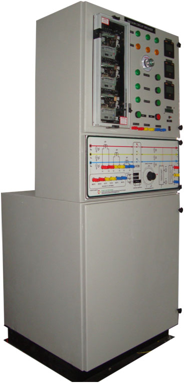
Test Panel
Panel with OCB Test set up (current injection source)
This panel consists of the following components
- Meter with Relay
- Variable ac current source with trip time indicator /meter
- Earth Fault SIMULATOR
Meter with Relay
- One number of IDMT OC Relay with necessary CT
- One number of Electromechanical Type Earth Fault Relay with necessary CT
Over Current Relay
- Type : Single Pole /element Over Current Relay
- CT Input : 5A
- PMS : 50% -200% in steps of 25%
- TMS : 1 to 1 in steps of 0.1s
- Function : IDMT
- Curve : IDMT curve of 3sec as per IEC-255
- Features : Self powered
- Hand reset type-Mechanical Flag Indicator
- Make : MEGAWIN (MCDG11)/AREVA (CDG11)
- One number of IDMT E/F Relay with necessary CT
E/F Current Relay
- Type : Single Pole /element E/F Relay
- CT Input : 2A
- PMS : 50% -200% in steps of 25%
- TMS : 1 to 1 in steps of 0.1s
- Function : IDMT
- Curve : IDMT curve of 3sec as per IEC-255
- Features : Self powered
- Hand reset type-Mechanical Flag Indicator
- Make : MEGAWIN (MCDG11)/AREVA (CDG11)
Variable ac current source with trip time indicator /meter
- One number of Variable current source of 0-30A is provided to test VCB
- One number of digital AC Ammeter is provided to indicate the Fault current in Amp
- Autotransformer is provided to adjust the current output.
- One number of Automatic trip time measurement circuit (ATTM Circuit) is provided
- One number START push button is provided in ATTM Circuit
- One number STOP push button is provided in ATTM Circuit
- One number LCD – Digital stop Clock is provided in ATTM Circuit to measure relay trip time in S , S/10 , S/100
- One number reset switch is provided in front panel to restart the digital stop clock
Earth Fault Simulator
This set up is designed to simulate the Earth Fault for ACB testing , This set up consists of
- One number of 3 phase induction motor /0.5HP/CG Make/3 PHASE 415VAC/ is provided to simulate Earth Fault
- Necessary Earth side CT & all necessary terminals are terminated in motor for Earth Fault simulation
- One number of Current limit resistor is provided to adjust/limit the Earth Fault current
Other Features
- OCB busbar input & output indicator is provided
- Necessary CT With suitable rating is provided
- Breaker trip status indicator with manual on/off switch
- All are mounted on a nice cabinet with diagram stickered on front panel.&230VAC@50Hz AC Input with power ON/OFF Switch
- Mimic diagram is printed on panel front plate for easy understanding
EXPERIMENTS
- Testing of OCB under Over current fault conditions (under different fault current & study the tripping characteristics)
- Testing of OCB under Earth fault conditions (under different fault current & study the tripping characteristics)
- Study the construction & operation of OCB