Generator Protection Simulation Experimental Unit
This set up is designed to study the various protection scheme of three phase Alternator (AC GENERATOR) set up using power systems protection relays. it consists of
- Power systems Protection Relays (Digital Relays)
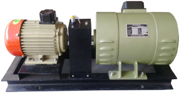
- 3Ø /1KVA Alternator -Prime mover set up – with drive
- Panel with Meter arrangements
- Power system Protection Relays
- Numerical 3 phase over current relay + earth fault relay (MAKE C&S)
- Numerical % differential relay (MAKE C&S /PLI)
- Numerical over voltage / under voltage relay /Negative sequence Relay (MAKE C&S)
- Reverse power relay (provided with Optional cost) (MAKE PLI)
- Microcontroller Synchronous relay (provided with Optional cost) (MAKE PLI)
- Numerical over/under frequency relay (provided with Optional cost) (MAKE C&S /PLI)
- 3Ø Alternator – Prime mover set up- with drive
This alternator set up is used to feed the 3 phase supply to the control panel for protection relay testing. This set up Consists of the following alternator motor setup provided for fault protection study purpose.
Specification (AC GENERATOR/Alternator)
- Type : 3Ø Alternator/Rotating Field Type
- Power : 1KVA
- Voltage Output : 415VAC
- Current : 3AMP
- Excitation Voltage : 200VDC (Filed)
- Current : 1AMP
- Speed : 1500 RPM
- Make : RAMSON
- Additional Features : 0,25,50,75,100% tapping’s in stator terminals ( all 3 phase) for fault creation
Specification (AC Motor/Prime Mover)
- Type : 3Ø AC Motor (Squirrel cage induction Motor)
- Power : 2 hp
- Voltage Output : 415VAC
- Current : 2.8AMP
- Speed : 1440 RPM
- Make : CG/KEC/SIEMENS
- The above Alternator and prime mover (AC Motor) is coupled with common base plate with necessary coupling arrangements.
- One number of speed sensor (Proximity) is fixed on the motor shaft with digital speed indicator is provided for speed measurement
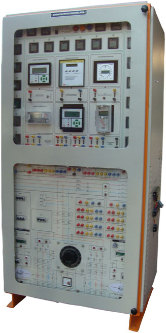
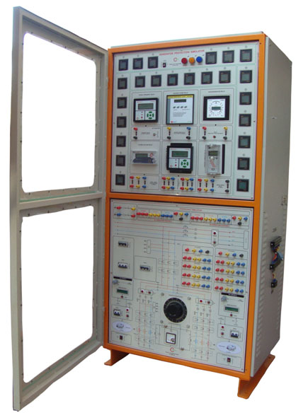
- Panel with Meter arrangements
Powder coated MS panel with stickered front panel is provided to fix all the relays, Digital meters , CT & PT , Prime mover AC drives etc , The detailed specifications is as below
AC Drive and Variable dc source
One number of AC DRIVE (VFD-Variable Frequency Drive) is provided for Prime mover speed adjustments. Specification is
- Type : AC Drive (IGBT based)
- Power : 2 hp
- Input : 1Ø /3Ø AC, 50Hz
- Output : 3Ø AC, 50Hz
- Make : DELTA- EQUIVALLENT
- Control : Front panel potentiometer (speed adjustment)
- This VFD drive is fixed on protection control Panel
- One number of field exciter box ( Input-230VAC , Output 200vdc,1Amp) is provided for Alternator Field excitation ( or AVR is provided for alternator field excitation)
Instruments Transformers (CT & PT)
- 5/1 A CT is provided for all current relays
- CT secondary outputs are terminated in front panel with necessary terminal identification for relay interconnection by user
- 220/110V or 63V PT is provided for all voltage & frequency & synchronizing relays
- CT secondary outputs are terminated in front panel with necessary terminal identification for relay interconnection by user
- All relays specification matched with GENERATOR specification using CT/PT’s
- All are mounted on a nice cabinet with necessary diagram indication
Digital Meters
- Three no. of ac digital ammeter provided for alternator -1 current measurement.
- Three no. of ac digital ammeter provided for (Alternator -2 or MAINS Side) current measurement.
- Three no. of ac digital voltmeter provided for load voltage measurement.
- Digital dc voltmeter is provided to measure alternator excitation voltage
Others features
- Two numbers of current limiting resistor-1.5A with banana terminations is provided for stator /EF fault creations
- 3 phase breakers & MCB’s are provided for protection &Necessary 3 phase indicators are provided
3 phase Load
One number of three phase Lamp load provided with diff-load selector switch is provided for alternator loading
- Input : 3 phase 415vac
- Capacity : 5 KVA
- Number of load ON/OFF switch :
List of experiments
- Study and Testing of Over current relay in generator protection system with IDMT relay Characteristics
- Study and Testing of Over voltage relay in generator protection system with IDMT relay Characteristics
- Study and Testing of under voltage relay in generator protection system with IDMT relay Characteristics
- Study and Testing of earth fault relay in generator protection system with IDMT relay Characteristics by creating E/F
- Study and Testing of Over frequency relay in generator protection system with IDMT &DMT relay Characteristics (optional)
- Study and Testing of under frequency relay in generator protection system with IDMT &DMT relay Characteristics(optional)
- Study and Testing of negative sequence relay in generator protection system with DMT relay Characteristics(optional)
- Study and Testing of generator reverse power protection using reverse power protection relay with DMT relay Characteristics(optional)