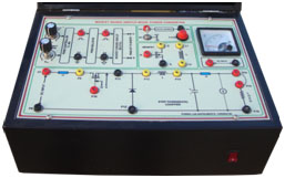
STUDY OF DC BUCK BOOST CONVERTER This set up is designed to study the BUCK (Step down) & Boost Type DC-DC Converter circuits. This set up consists ofPWM ControllerMOSFET Power circuitDC Power supply.PWM Controller:One number of TL494 IC Based PWM controller for converter power circuitsPotentiometer is provided to vary the PWM Duty cycle ratioPotentiometer is provided to vary the PWM FrequencyNecessary test points are provided to study the PWM ControllerPWM output is terminated in connector for MOSFET power circuit patchingMOSFET Power circuit:One number of IRF250 Power MOSFET with proper heat sink is provided for power circuitSeparate power circuit for Buck & Boost converterOne number of High Frequency Inductor and output filter is providedOne number of Fixed Load resistor is providedPWM ISOLATOR IC and DRIVER ICs are provided for MOSFET power circuits PWM amplificationsNecessary test points & PWM input connector are providedSpecificationsBuck ConverterPower circuit Inputs : 5-20VDCOutput : 5VDC @ 1ABoost ConverterPower circuit Inputs : 10-15VDCOutput : 20VDC @ 0.5AOne number of Fixed dc power supply is provided for power circuit inputs