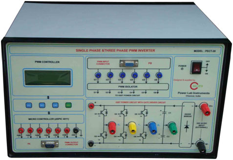
This trainer is designed to study the working principle of IGBT based DC-AC inverter ( single phase & 3 phase) using various PWM techniques. It consists of
IGBT PWM Controller & 3 Phase IGBT Power Circuit
RL Load & DC Power supply
PWM controller
Digital IC (Dspic4011) based Single phase & 3 Phase PWM generation
6 Numbers of PWM Outputs with Frequency & Modulation index variation
Digital keys for PWM adjustment
LCD is provided to display PWM Details
5 khz Switching frequency operation
PWM outputs are terminated by front panel Connector.
IGBT power module (Voltage source Inverter)
3 Phase Voltage source inverter Power circuit using 6 number of IGBT Rating @ 600V , 20A
IGBT is fixed with suitable heat sink and snubber circuit for protection
IGBT Power circuit input and outputs are terminated by suitable rating banana connectors in front panel with necessary indication
One number of diode rectifier ( 600V @ 35A ) is provided to converter input AC voltage to DC Bus voltage
DC Capacitor is provided ( centre point type) at diode rectifier output side for Filter
Six Number of PWM Isolator IC (6N137) is used to isolate All the six PWM signals input
One number of +15V@1amp fixed dc power supply is provided for PWM Isolator input side for power excitation
Built in IGBT Gate Driver (IR2112)is provided in SPM for IGBT Gate signal amplification
Power Circuit Input 0-30V DC
Output : 3 Ø 20V @ 2A , Variable Voltage , Variable frequency