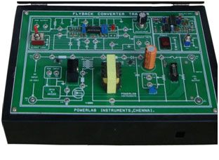
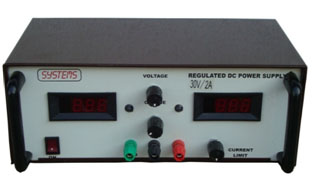
Previous Next DC –DC Fly back Converter This set up is designed to study the Flyback type BUCK (Step down) switch mode regulator circuits. This set up consists of,PWM ControllerMOSFET Power circuitDC Power supply.PWM Controller:One number of TL494 IC Based PWM controller for converter power circuitsPotentiometer is provided to vary the PWM Duty cycle ratioPotentiometer is provided to vary the PWM FrequencyNecessary test points are provided to study the PWM ControllerPWM output is terminated in connector for MOSFET power circuit patchingMOSFET Power circuit:One number of IRF250 Power MOSFET with proper heat sink is provided for power circuitOne number of High Frequency transformer and output filter is providedOne number of Fixed Load resistor is providedPWM ISOLATOR IC and DRIVER ICs are provided for MOSFET power circuits PWM amplificationsNecessary test points & PWM input connector are providedCurrent sensing resistors are provided in varies place for current wave form measurementsSpecificationsPower circuit Inputs : 5-20VDCOutput : 5VDC @ 1AMPPower supplyOne number of 0-30v@2A Variable dc power supply with ammeter & Voltmeter is provided for power circuit inputs