To Study Speed Control Of Seperately Excited Dc Motor Using Mosfet/Igbt Chopper ( 4 Quadarant Chopper Drive)
This set up consists of
- Microcontroller based PWM Controller
- IGBT Power Module
- 1 HP DC Motor Load set up


Microcontroller based PWM Controller
This PWM controller is designed based on Dspic30f4011 controller chip specially designed for Power Electronics & Motor control applications from “MICROCHIP” company and this controller can be used to generate PWM Signals for SCR, IGBT based power electronics application like DC-AC Inverter ,DC-DC Chopper & SCR converter based AC/DC/BLDC Switched Reluctance Motor (SRM) control application. PWM output of this controller can be directly interfaced with Power Module through External cable connection.
Features
- Includes High-Performance Microchip dsPIC30F4011 Microcontroller with 48kb Internal Flash Program Memory
- 6 Numbers of PWM Outputs up to 15KHZ of switching frequency
- RS232 Connection with MAX232
- Internal EEPROM
- Five 16-bit Timers
- Power, Programming and Test LED’s
- 2MB PROM & 24 Mhz clock speed
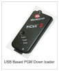
- USB – PGM Down loader
- 6 Numbers of ADC input
- QEP Sensor /Hall sensor/Speed sensor(Proximity)Interface
- PWM increment & decrement key
- Reset switch & LED’s for Sensor status
- 20 X 4 LCD screen
- PWM outputs are terminated by 34 pin FRC Connector
USB Based Program downloader
- One number of USB based program downloader is provided
- IGBT power module (Voltage source Inverter)
This power module is designed by using IGBT based Smart Power Module (SPM) from “FAIRCHILD SEMICONDUCTORS” for AC/DC Motor control application. This power module can be used for AC, DC, BLDC, PMSM Motor application by proper external PWM controller interfacing (like Dspic , FPGA & DSP). This Module consists of
IGBT
- One Number of SPM-Smart Power Module ( Model FSBB20CH60B ) Rating @ 600V , 20A based Voltage source inverter Power circuit
- SPM-IGBT is fixed with suitable heat sink and snubber circuit for protection
- IGBT Power circuit input and outputs are terminated by suitable rating banana connectors in front panel with necessary indication
DIODE RECTIFIER
- One number of diode rectifier ( 600V @ 35A ) is provided to converter input AC voltage to DC Bus voltage
- DC Capacitor is provided ( centre point type) at diode rectifier output side for Filter
- Analogue DC Voltmeter is provided to measure DC Bus voltage
PWM ISOLATOR
- Six Number of PWM Isolator IC (6N137) is used to isolate All the six PWM signals input
- One number of +15V@1amp fixed dc power supply is provided for PWM Isolator input side for power excitation
- One number of +5V@1amp fixed dc power supply is provided for PWM Isolator Output side power excitation
PWM Driver
- Built in IGBT Gate Driver is provided in SPM for IGBT Gate signal amplification.
SENSORS
- 3 numbers of Hall effect current sensor @ 25A is provided for 3Ø output AC/DC Current measurement
- 1 numbers of Hall effect current sensor @ 25A is provided for Input DC bus Current measurement
- Op-Amp based Signal conditioner circuits are provided in all sensors for output current signals amplifications
- All current sensor signal conditioner circuit outputs are terminated in front panel by suitable connectors
PROTECTION CIRCUIT
- One number of automatic trip circuit is provided for O/C protection
- LED is provided for trip status indication
- Reset switch is provided for TRIP RESET
CONNECTORS
- One number of 34 pin FRC Connector is provided for PWM input signal input and feed back
- Banana connectors are provided for AC input
- Banana connectors are provided for 3 phase output
- Test points are provided for PWM signal and Current wave form measurements
- MCB is provided at input side for Input supply ON/OFF
SPECIFICATION
- Power Circuit
- Input : 0-230VAC , 50 HZ (or) 0-300VDC
- Output : 3 Ø 200V @ 5A , Variable Voltage ,
Variable frequency ( OR) 0 +/- 280VDC
- PWM Section
- Number of PWM Input : 6
- Maximum PWM Frequency : 15KHZ
- PWM Level : 0-5V (TTL)
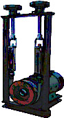
DC Shunt Motor with load set up
- Type : DC Shunt Motor
- Power : 1 hp
- Voltage : 200vdc for Armature & Field
- Speed : 1500 RPM
- Feedback sensor : Proximity sensor
- Loading : spring balance loading
- Make : BENN /RAMSON/OMEGA
Spring balance Loading
- One number Brake DRUM with spring balance set up is coupled with the above motor
- Two numbers of dial indication for Load in Kg measurement All are mounted on a powder coated mechanical set up.